Construction Documentation and Structural Drawings with Fespa IS
The design engineer has the ultimate control of the analysis and design procedure.
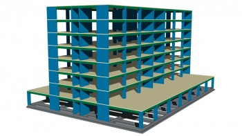
Fespa IS covers all phases of a structural design project from the structural analysis to the production of a fully integrated construction documentation and series of drawings. After the completion of all calculations structural drawings for each floor are automatically created, automatic and consistent column and beam details are also derived.
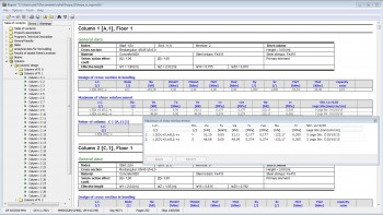
The program produces a very comprehensive report specially designed to facilitate cross-checking from the reviewers. It is well organized, conservative on paper consumption and can deliver detailed output for any beam, column, footing etc chosen. Reports are linked directly to the model so changes are automatically updated.
Report
With the «Report» program, the design engineer can edit the document according to their preferences:
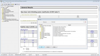
- The extent of the report can be adjusted, as a variety of filters are offered. Furthermore, the engineer can create their own templates of filter groups.
- Error / Warning messages with explanation based on relevant paragraphs of the Standards and recommended ways of resolving the specific error.
- Export of tables in tek / csv/ html files so that they can also be used, for example, in the structural drawings.
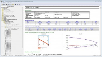
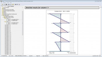
Detailed results for Columns
- Simultaneous presentation of graphics and text data.
- Design envelope for shear forces and bending moments in columns.
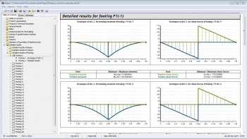
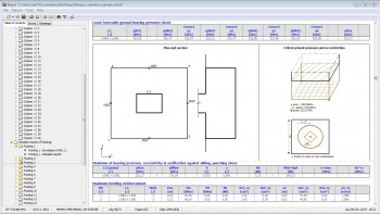
Detailed results for Footings
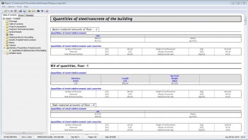
Bill of quantities for the building
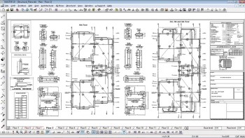
Drawings
For the editing of drawings multiple colours, line types, line densities and hatches are provided to describe the various members (slabs, beams, columns, footings).
Dimensions may be added and calculated automatically and there are various font texts that can be used for the dimension texts.
Captions, symbols,tags and heights can be easily inserted and modified.
Beam Elevations
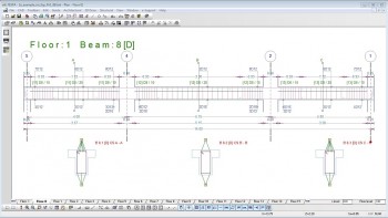
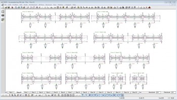
After the analysis, by selecting the desired beam, the add-on module «Beam elevations» automatically creates a file with the corresponding beam elevation. Beam elevations include longitudinal rebar size, stirrup size, section marks, walls, columns.
The design engineer has the option to edit the details (change rebar diameters, the stirrup type, etc) then save and print them.
Column Details
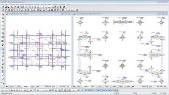
The column details may be edited by the commands of the «Cross-section» tool, the «Cross-section rebar» tool, etc.


